The history of high density (HD) Wi-Fi deployments in stadiums and arenas is short. Yet the the amount of change that occurred is significant; both in terms of how these networks are deployed and why.
Venue operators, manufacturers, and integrators are still grappling with the particulars of HD Wi-Fi in large open environments, even though there are a substantial number of deployed high quality implementations. Below, I’ve shared our perspective on the evolution of HD Wi-Fi design in stadiums and arenas and put forth questions that venue operators should be asking to find a solution that fits their needs and their budget.
AmpThink’s background in this field
Over the past 5 years, our team has been involved in the deployment of more than 50 high-density Wi-Fi networks in stadiums throughout North America. In that same period, the best-practices for stadium HD Wi-Fi design have changed several times, resulting in multiple deployment methodologies.
Each major shift in deployment strategy was intended to increase total system capacity [1]. The largest gains have come from better antenna technology or deployment techinques that better isolated access point output resulting in gains in channel re-use.
What follows is a summary of what we’ve learned from the deployments we participated in and their significance for the future. Hopefully, this information will be useful to others as they embark on their journeys to purchase, deploy, or enhance their own HD Wi-Fi networks.
In the beginning: All about overhead
Editor’s note: This post is part of Mobile Sports Report’s new Voices of the Industry feature, in which industry representatives submit articles, commentary or other information to share with the greater stadium technology marketplace. These are NOT paid advertisements, or infomercials. See our explanation of the feature to understand how it works.
Designers of first generation of HD Wi-Fi networks were starting to develop the basic concepts that would come to define HD deployments in large, open environments. Their work was informed by prior deployments in auditoriums and convention centers and focused on using directional antennas. The stated goal of this approach was to reduce co-channel interference [2] by reducing the effective footprint of an individual access point’s [3] RF output.
However the greatest gains came from improving the quality of the link between clients and the access point. Better antennas allowed client devices to communicate at faster speeds which decreased the amount of time required to complete their communication, making room for more clients on each channel before a given channel became saturated or unstable.
Typically, Stadium Antennas are installed in the ceilings above seating and/or on the walls behind seating because those locations are relatively easy to cable and minimize cost. We categorize these deployments as Overhead Deployments.
From overhead to ‘front and back’
First generation overhead deployments generally suffer from a lack of overhead mounting locations to produce sufficient coverage across the entire venue. In football stadiums, the front rows of the lower bowl are typically not covered by an overhang that can be used for antenna placement.
These rows are often more than 100 feet from the nearest overhead mounting location. The result is that pure overhead deployments leave some of the most expensive seats in the venue with little or no coverage. Further, due to the length of these sections, antennas at the back of the section potentially service thousands of client devices [4].
As fans joined these networks, deployments quickly became over-loaded and generated service complaints for venue owners. The solution was simple — add antennas at the front of long sections to reduce the total client load on the access points at the back. It was an effective band-aid that prioritized serving the venues’ most important and often most demanding guests.
This approach increased the complexity of installation as it was often difficult to cable access points located at the front of a section.
And for the first time, antennas were placed where they were subject to damage by fans, direct exposure to weather, and pressure washing [5]. With increased complexity, came increased costs as measured by the average cost per installed access point across a venue.
Because these systems feature antennas at the front and rear of each seating section, we refer to these deployments as ‘Front-to-Back Deployments.’ While this approach solves specific problems, it is not a complete solution in larger venues.
‘Filling In’ the gaps
Data collected from Front-to-Back Deployments proved to designers that moving the antennas closer to end users:
— covered areas that were previously uncovered;
— increased average data rates throughout the bowl;
— used the available spectrum more effectively; and
— increased total system capacity.
The logical conclusion was that additional antennas installed between the front and rear antennas would further increase system capacity. In long sections these additional antennas would also provide coverage to fans that were seated too far forward of antennas at the rear of the section and too far back from antennas at the front of the section. The result was uniform coverage throughout the venue.
In response, system designers experimented with hand rail mounted access points. Using directional antennas, coverage could be directed across a section and in opposition to the forward-facing antennas at the rear of the section and rear-facing antennas at the front of a section. These placements filled in the gaps in a Front-to-Back Deployment, hence the name ‘In-Fill Deployment.’
While these new In-Fill Deployments did their job, they added expense to what was already an expensive endeavor. Mounting access points on handrails required that a hole be drilled in the stadia at each access point location to cable the installed equipment. With the access point and antenna now firmly embedded in the seating, devices were also exposed to more traffic and abuse. Creative integrators came to the table with hardened systems to protect the equipment – handrail enclosures. New costs included: using ground-penetrating radar to prepare for coring; enclosure fabrication costs; and more complex conduit and pathway considerations. A typical handrail placement could cost four times the cost of a typical overhead placement and a designer might call for 2 or 3 handrail placements for every overhead placement.
Getting closer, better, faster: Proximate Networks
In-Fill strategies substantially solved the coverage problem in large venues. Using a combination of back of section, front of section, and hand-rail mounted access points, wireless designers had a tool box to deliver full coverage.
But with that success came a new problem. As fans discovered these high density networks and found new uses for them, demands on those networks grew rapidly, especially where teams or venue owners pushed mobile-device content strategies that added to the network load. In-spite of well placed access points, fan devices did not attach to the in-fill devices at the same rate that they attached to the overhead placements [6]. In-fill equipment remained lightly used and overhead placements absorbed hundreds of clients. Gains in system capacity stalled.
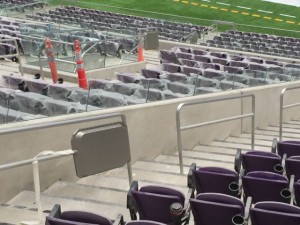
Close-up look at U.S. Bank Stadium railing enclosure during final construction phase, summer 2016. Credit: Paul Kapustka, MSR
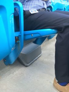
Proximate networks come in two variations: handrail only and under seat only. In the hand rail only model, the designer eliminates overhead and front of section placements in favor of a dense deployment of hand rail enclosures. In the under seat model, the designer places the access point and antenna underneath the actual seating (but above the steel or concrete decking). In both models, the crowd becomes an important part of the design. The crowd attenuates the signal as it passes through their bodies resulting in consistent signal degradation and even distribution of RF energy throughout the seating bowl. The result is even access point loading and increased system capacity.
An additional benefit of embedding the access points in the crowd is that the crowd effectively constrains the output of the access point much as a wall constrains the output of an access point in a typical building. Each radio therefore hears fewer of its neighbors, allowing each channel to be re-used more effectively. And because the crowd provides an effective mechanism for controlling the spread of RF energy, the radios can be operated at higher power levels which improves the link between the access point and the fan’s device. The result is more uniform system loading, higher average data rates, increased channel re-ue, and increases in total system capacity.
While Proximate Networks are still a relatively new concept, the early data (and a rapid number of fast followers) confirms that if you want the densest possible network with the largest possible capacity, then a Proximate Network is what you need.
The Financials: picking what’s right for you
From the foregoing essay, you might conclude that the author’s recommendation is to deploy a Proximate Network. However, that is not necessarily the case. If you want the densest possible network with the largest possible capacity, then a Proximate Network is a good choice. But there are merits to each approach described and a cost benefit analysis should be performed before a deployment approach is selected.
For many venues, Overhead Deployments remain the most cost effective way to provide coverage. For many smaller venues and in venues where system utilization is expected to be low, an Overhead deployment can be ideal.
Front-to-Back deployments work well in venues where system utilization is low and the available overhead mounting assets can’t cover all areas. The goal of these deployments is ensuring usable coverage, not maximizing total system capacity.
In-fill deployments are a good compromise between a coverage-centric high density approach and a capacity-centric approach. This approach is best suited to venues that need more total system capacity, but have budget constraints the prevent selecting a Proximate approach.
Proximate deployments provide the maximum possible wireless density for venues where connectivity is considered to be a critical part of the venue experience.
Conclusion
If your venue is contemplating deploying a high density network, ask your integrator to walk you through the expected system demand, the calculation of system capacity for each approach, and finally the cost of each approach. Make sure you understand their assumptions. Then, select the deployment model that meets your business requirements — there is no “one size fits all” when it comes to stadium Wi-Fi.

Bill Anderson, AmpThink
His work with mobile computing and wireless networks in distribution and manufacturing afforded him a front row seat to the emergence of Wi-Fi and the transformation of Wi-Fi from a niche technology to a business critical system. Since 2011 at AmpThink Bill has been actively involved in constructing some of the largest single venue wireless networks in the world.
Footnotes
^ 1. A proxy for the calculation of overall system capacity is developed by multiplying the average speed of communication of all clients on a channel (avg data rate or speed) by the number of channels deployed in the system (available spectrum) by the number of times we can use each channel (channel re-use) or [speed x spectrum x re-use]. While there are many other parameters that come into play when designing a high density network (noise, attenuation, reflection, etc.), this simple equation helps us understand how we approach building networks that can support a large number of connected devices in an open environment, e.g. the bowl of a stadium or arena.
^ 2. Co-channel interference refers to a scenario where multiple access points are attepting to communicate with client devices using the same channel. If a client or access point hears competing communication on the channel they are attempting to use, they must wait until that communication is complete before they can send their message.
^ 3. Access Point is the term used in the Wi-Fi industry to describe the network endpoint that client devices communicate with over the air. Other terms used include radio, AP, or WAP. In most cases, each access point is equipped with 2 or more physical radios that communicate on one of two bands – 2.4 GHz or 5 GHz. HD Wi-Fi deployments are composed of several hundred to over 1,000 access points connected to a robust wired network that funnels guest traffic to and from the internet.
^ 4. While there is no hard and fast rule, most industry experts agree that a single access point can service between 50 and 100 client devices.
^ 5. Venues often use pressure washers to clean a stadium after a big event.
^ 6. Unlike cellular systems which can dictate which mobile device attaches to each network node, at what speed, and when they can communicate, Wi-Fi relies on the mobile device to make the same decisions. When presented with a handrail access point and an overhead access point, mobile devices often hear the overhead placement better and therefore prefer the overhead placement. In In-Fill deployments, this often results in a disproportionate number of client devices selecting overhead placements. The problem can be managed by lowering the power level on the overhead access point at the expense of degrading the experience of the devices that the designer intended to attach to the overhead access point.
